Most people who need a generator also need a transfer switch. There are thousands of choices. Here is some information to help you chose the right one.
Why do I need a transfer switch?
Do I need a manual or automatic transfer switch?
Where should I install my transfer switch?
What is a NEMA enclosure on a transfer switch?
What is the difference between an ASCO secure and non-secure enclosure?
Can I use my GFCI protected generator with a transfer switch?
What is the difference between service and non-service entrance rated transfer switches?
What is the difference between a solid and a switched neutral?
What is the difference between an open and closed transition?
How many poles does my transfer switch need?
What are NFPA 70 700.3 (f) requirements?
What should I do if my standby generator doesn’t crank or generator cranks and doesn’t run?
What if my standby generator doesn’t transfer and/or generator light doesn’t come on?
What if my transfer switch won’t transfer to utility and/or the utility acceptable doesn’t come on?
What if my transfer switch won’t transfer?
What if my transfer switch goes back to utility, but my standby generator keeps running?
What should I do if my transfer switch exercise is not working?
Why do I need a transfer switch?
Whether you purchased a portable, permanently mounted, or power take-off (PTO) generator you will need to figure out how you will want to get power from the generator to your equipment.
1. Plug equipment directly into the generator.
This is a simple and cost-effective way. There are some disadvantages. For example, you will not be able to easily power your furnace or AC; for a light source, you will need lamps. There is also the hazard of the extension cords running through the building. It is also essential that the generator is far enough away from the building to prevent carbon monoxide from getting indoors.
2. Backfeeding
www.esfi.org
Some people (not us) will recommend backfeeding. Backfeeding is when the flow of electrical energy is in reverse and is injected back into the building without a transfer switch. This is illegal, may be deadly, and should never be attempted – under any circumstances. Backfeeding power into a building has the risk of feeding generator power onto the utility lines. This can cause harm or death to a utility worker when they come to repair a power line. They aren’t expecting power present in the line and you could be criminally prosecuted. Even if you have the main breaker off, this is an illegal practice.
Backfeeding will also cause damage not only to the generator, but everything around it. A huge surge of back-fed power will blow up the generator. This causes a huge fire risk. Take time to read this story submitted by Rick Berry, the Electrical Safety Officer in Vancouver, Canada. https://www.electricgeneratorsdirect.com/stories/13-How-NOT-to-Connect-a-Portable-Generator.html
3. Transfer Switch
The simplest and recommended way is installing a transfer switch.
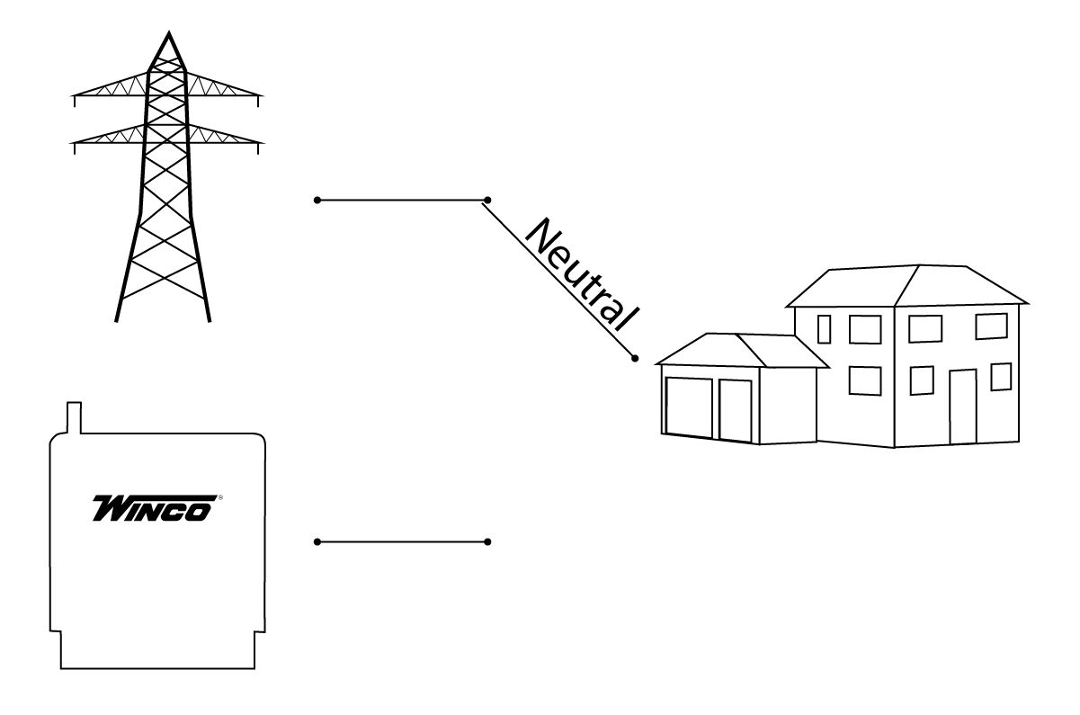
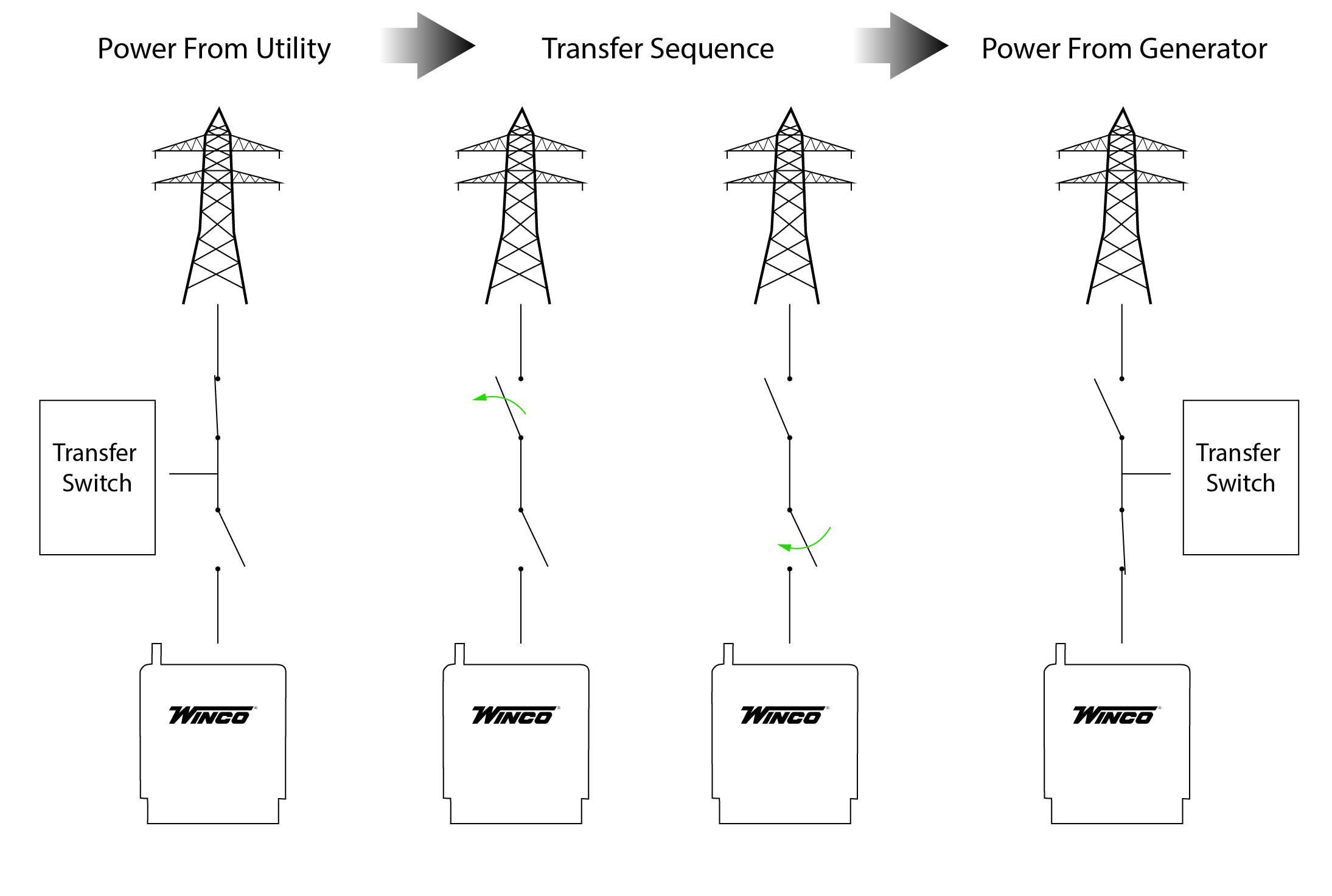
HOW DOES A TRANSFER SWITCH WORK?
A transfer switch is connected to the utility power, generator power and the building load. Once the power goes out, the switch will disconnect the building from one source of power (utility) then make the connection to the generator. The transfer switch is mechanically interlocked making it impossible to connect the building to both the generator and utility at the same time. This is the same concept for both manual and automatic switches.
Do I need a manual or automatic transfer switch?
Manual and automatic transfer switches are an important accessory when it comes to safely switching from utility power to backup power.
How they work
1. Manual transfer switch
When the power fails you need to get your generator set up. Normally you wheel it outside and place it where exhaust fumes cannot seep into windows, doors or vents. Next you need to connect the power cord between the generator and transfer switch. Once you have the generator running you will go to the transfer switch and manually switch from utility to generator power. Once you notice the utility power is back on you reverse the process.
2. Automatic transfer switch
The transfer switch will detect a utility failure and send a signal to the generator to start up. When the generator is at the correct voltage, usually within about 10-30 seconds, the transfer switch will connect power.
As soon as utility power is detected, the switch will signal the generator to shut down, and switch back to the utility power source.
Pros and cons of each system
1. Manual Transfer Switch
Pros –
- Your generator is most likely a portable generator and you will be able to move it around.
- Cost effective.
- You have full control.
Cons –
- You have to be present to switch between power sources.
- More work.
- Requires a little technical skill.
- You can run on generator power long after utility power is restored if you aren’t paying attention.
2. Automatic Transfer Switch
Pros –
- Easy to use.
- You do not have to be on site.
- Automatically tests itself.
- Less down time between transfer.
Cons –
- More expensive.
- Generator is permanently mounted.
Matching a transfer switch to a generator
Manual and automatic transfer switches can work with any type of generator. Generally, if you have a portable, towable, or PTO generator, you will select a manual transfer switch. Standby models, such as our PSS or diesel units, you will use an automatic transfer switch. If you have any questions or concerns, give us a call or contact your local electrician.
Where should I install my transfer switch?
Where you install the transfer switch will depend on the type of switch and what type of generator you will be using. The following installations will work for both manual and automatic transfer switches.
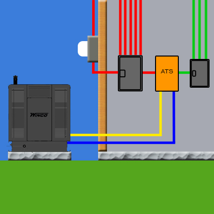
Emergency Distribution:
The transfer switch is installed between a main panel and a sub panel. The main panel connects to the non-essential loads. The sub panel connects to the essential loads. In the event of an outage, the transfer switch will only transfer power to the essential load panel.
This type of installation allows you to purchase a smaller generator and a smaller amperage transfer switch. As a result, it will keep costs down.
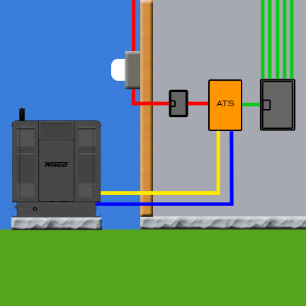
Full Load (Non-SE Rated):
The transfer switch will be located after the service disconnect panel of the building. There is the option to manually switch breakers off on any load you do not want to power.
You will want to size your generator and transfer switch amperage to match the load.
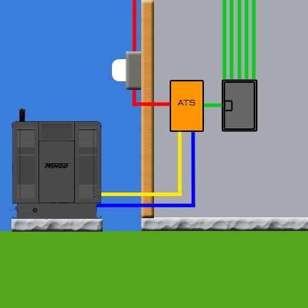
Full Load (SE Rated):
An SE rated transfer switch has a service disconnect breaker installed. Therefore, the switch will be installed directly to the utility power entering the building. The main panel will have the essential loads connected. There is the option to manually switch breakers off on any load you do not want to power.
You will want to size your generator and transfer switch amperage to match what will be powered with the generator.
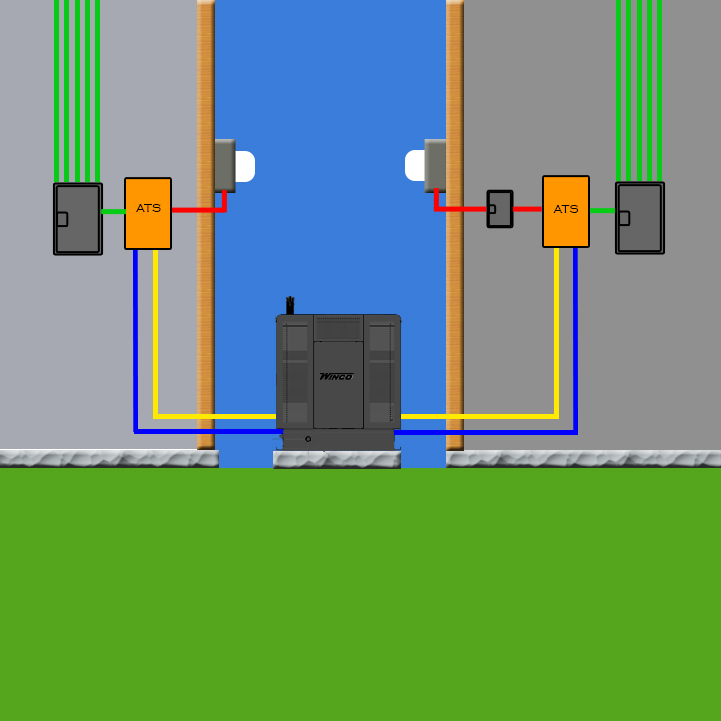
Multiple Services:
One generator can provide backup power to multiple services. You can install the transfer switches in any variation of the three installations mentioned above.
You will want to size the generator large enough to run normal loads and start large motors.
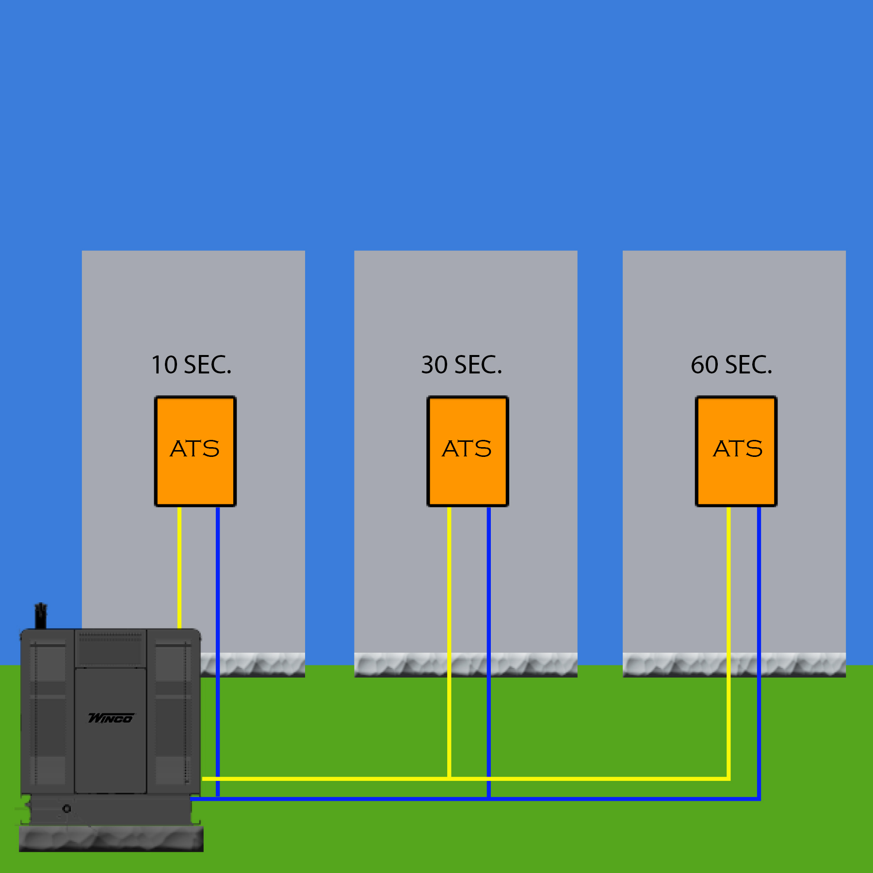
Transfer switch as a Load Control Device:
Starting large motors at the same time will require a large generator to deal with the inrush. A cost-effective solution is to install multiple transfer switches. By setting the transfer delay in staggered intervals each load will be added to the generator separately reducing total inrush. You can install the transfer switches in any variation of the three installations mentioned above on each load.
Be sure to size the generator so it will be able to run all connected loads and also have enough amperage to start the last motor.
What is a NEMA enclosure on a transfer switch?
A transfer switch can be damaged or create dangerous conditions if it is exposed to dirt or water. Therefore, it is essential that the transfer switch has an enclosure designed for the location and the risks it will be exposed to.
NEMA stands for National Electrical Manufacturers Association. NEMA represents nearly 325 electrical equipment and medical imaging manufacturers who make safe, reliable, and efficient products and systems.
For those who like the full technical definition keep reading. We included some pictures for the visual learners.
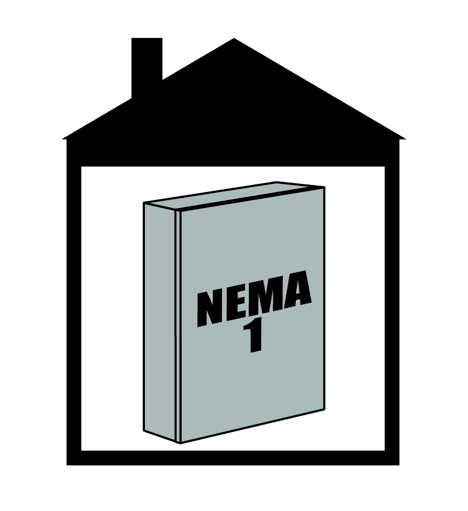
NEMA 1
For indoor use only.
The NEMA 1 enclosure protects personnel from gaining easy access to hazardous parts. Also, it will protect the equipment inside the enclosure of falling dirt.
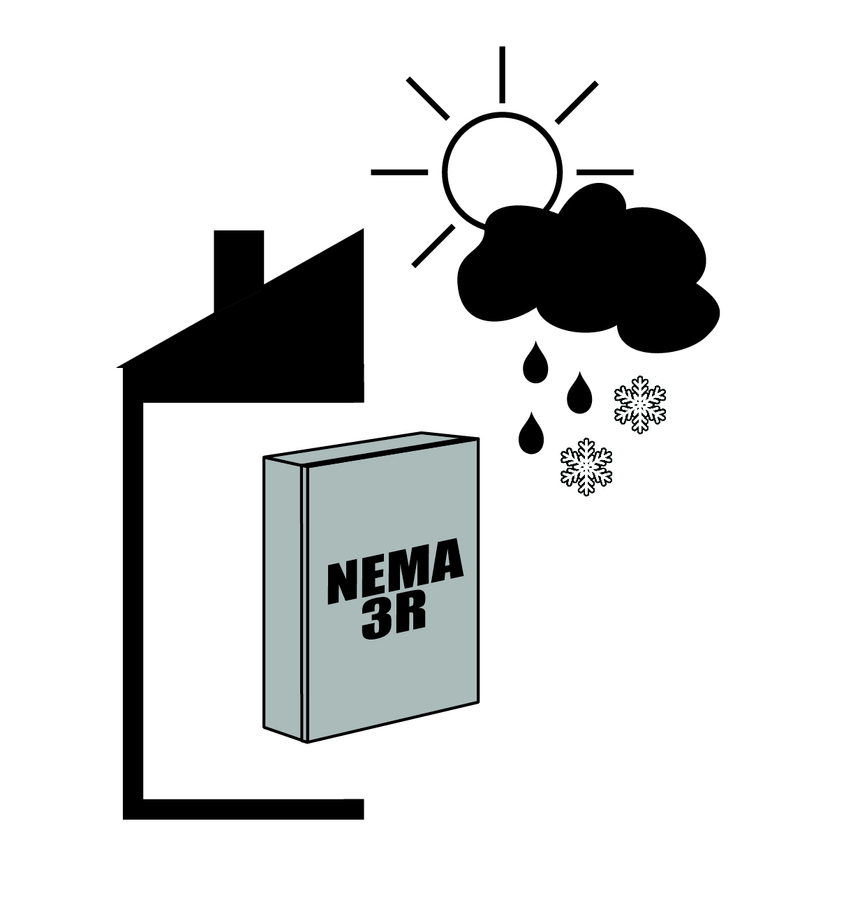
NEMA 3R
For indoor or outdoor use.
The NEMA 3R enclosure protects personnel from gaining easy access to hazardous parts. Also, it will protect the equipment inside the enclosure of falling dirt, and the formation of ice. It also has an ingress protection of rain, sleet, snow.
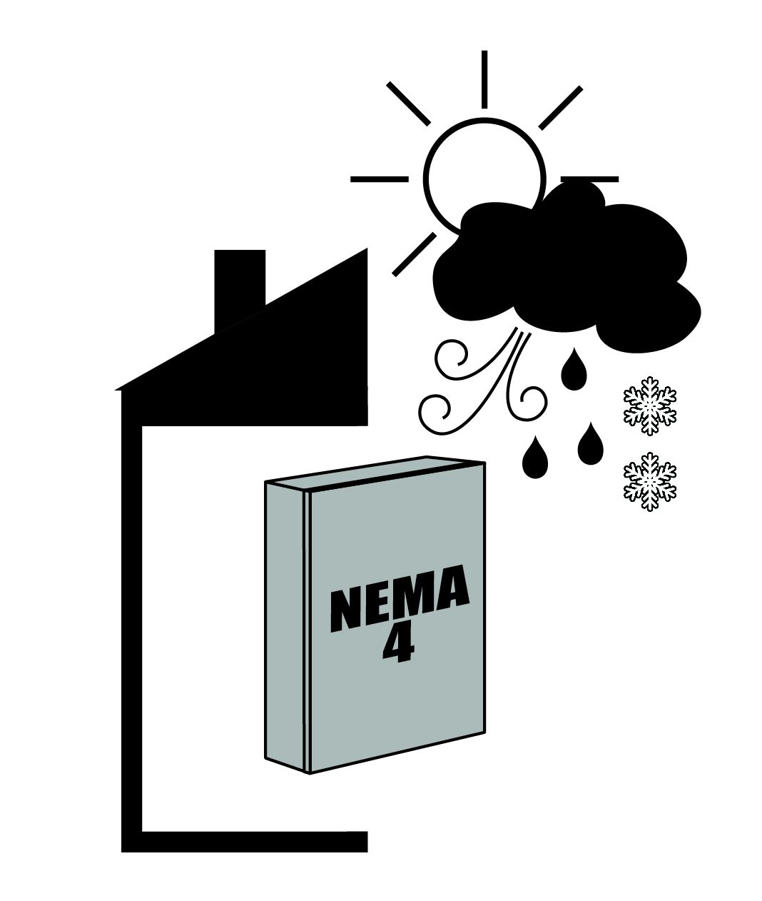
NEMA 4
For indoor or outdoor use.
The NEMA 4 enclosure protects personnel from gaining easy access to hazardous parts. Also, it will protect the equipment inside the enclosure of falling dirt, windblown dust, rain, sleet, snow, and the formation of ice. It also has an ingress protection of splashing water, hose directed water.
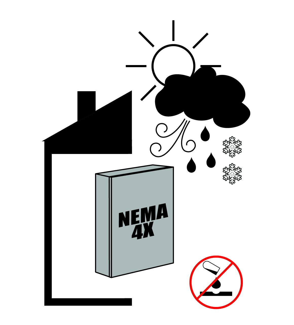
NEMA 4X
For indoor or outdoor use.
The NEMA 4X enclosure protects personnel from gaining easy access to hazardous parts. Also, it will protect the equipment inside the enclosure of windblown dust, rain, sleet, snow, additional level of protection against corrosion, and the formation of ice. It also has an ingress protection of splashing water, hose directed water.
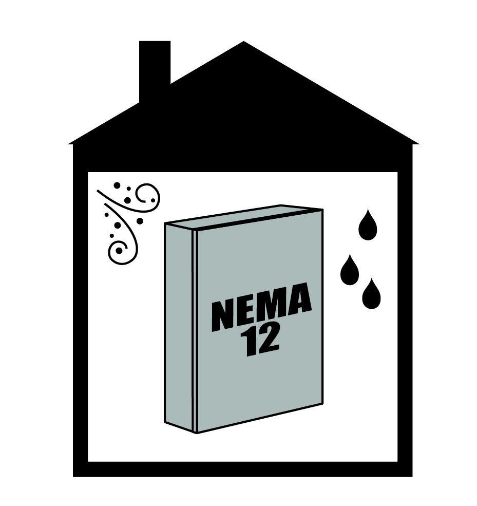
NEMA 12
For indoor use only.
The NEMA 12 enclosure (without knockouts) protects personnel against access to hazardous parts. Also, it will protect the equipment inside the enclosure of falling dirt, circulating dust, fibers. It also has an ingress protection of dripping and a light splashing of water.
What is the difference between an ASCO secure and non-secure enclosure?
When you think of an item being “secure”, like us, you probably think that something is lockable. In most circumstances, you are right. However, when ASCO says their switch has a secure enclosure, they are saying that the enclosure has extra protection from UV rays. All ASCO transfer switches require a key, tool or both to gain access to live parts. Not all ASCO transfer switches are protected from potential harmful effects of UV radiation.
Non-Secure
These enclosures have a single door access to the inside equipment. Controls and displays are mounted in the door, thus they are exposed to direct sunlight and other environmental conditions.
If you are installing the transfer switch in an area where UV protection isn’t a main concern, the non-secure enclosure would be a great choice.
Secure
Secure enclosures have a door-over-door construction, therefore, protecting the controls and displays from sunlight with some extra protection from precipitation.
Solar Radiation Exposure Map
High UV radiation levels, extreme temperatures, and conditions such as elevated humidity, high altitude, and air pollution, may increase the rate of degradation of display and control materials.
Can I use my GFCI protected generator with a transfer switch?
First, let’s discuss what GFCI protected means. GFCI stands for ground-fault circuit interrupter. You will recognize the outlets in your home, they are the ones with test and reset buttons. This is to eliminate the risk of an electric shock. On many of our generators, GFCI protection is part of the main line circuit breaker.
You can use a transfer switch with a full panel GFCI protected generator. When looking at transfer switches, you will need one with a switched neutral.
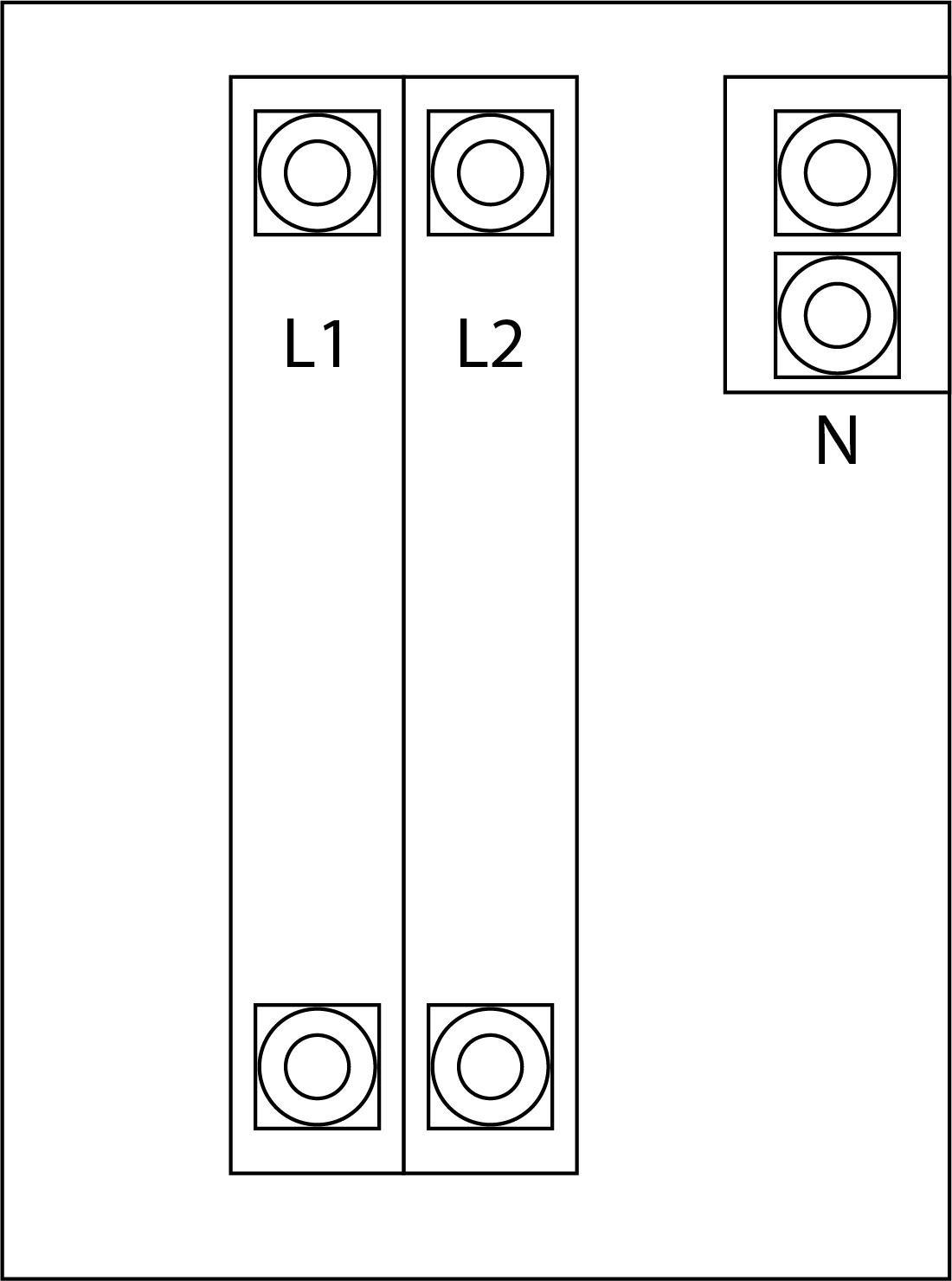
3-POLE SWITCHED NEUTRAL
A 3-pole transfer switch with a switched neutral is single phase. The switching mechanism will break the two hot legs of the circuit, in either direction, before the neutral is broken. It will then close the neutral before the two hot legs close, preventing the generator’s circuit breakers from nuisance tripping and protects inductive motors and sensitive loads.
This style of switched neutral transfer switch is also recommended for safe use with any generator that has a bonded neutral.
What is the difference between service and non-service entrance rated transfer switches?
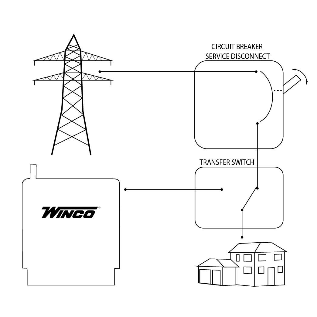
The National Electric Code (NEC) requires a way for disconnecting the electrical service where it enters a building. This main circuit breaker prevents the building from demanding too much current from the utility creating dangerous conditions. This circuit breaker may be in a separate panel or part of a service entrance rated transfer switch.
CB Service Disconnect
Click to enlarge
Non-Service Entrance Rated
There isn’t any over-current protection within a non-service entrance rated transfer switch. Therefore, when you install this type of transfer switch, it will be after the service disconnect panel.
If you find a non-fusible manual transfer switch, it does not have over-current protection. Non-fusible switches are not service entrance rated and cannot have the over-current protection added.
SE Rated Switch
Click to enlarge
Service Entrance Rated
Service entrance switches will have a service disconnect at the utility side. This installation requires less components, making it ideal for new construction, which can be more cost effective.
What is the difference between a solid and a switched neutral?
While searching for the right transfer switch, you will want to know how your application requires the neutral to be handled. The rules vary by application and in some cases depend upon the authority having jurisdiction (Local electrical inspector).
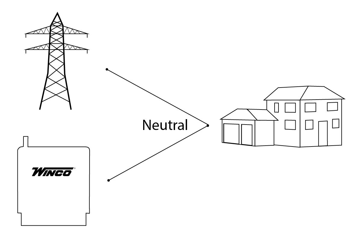
Solid Neutral
A solid neutral switch provides basic load switching. The neutral of the generator, utility and building are permanently connected inside the transfer switch. The transfer only switches the hot (power) leads. In this application you need one pole on the switch for each hot lead.
Switched Neutral
What is the difference between an open and closed transition?
When choosing a transfer switch, you will have to decide if you need an open or closed transition transfer switch. Basically, you need to ask yourself if you have critical loads that cannot have disruption of power, not even for a split second.
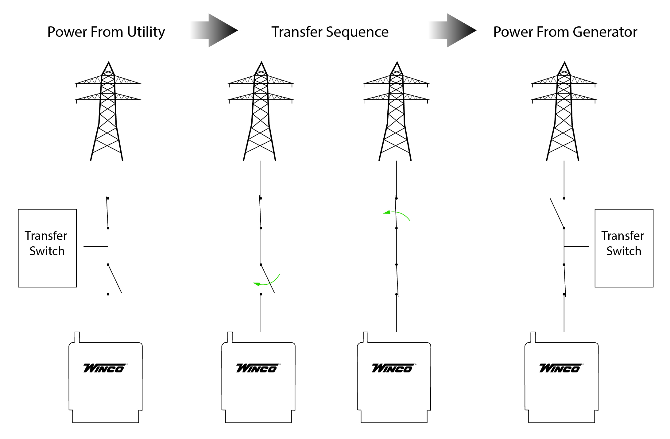
OPEN TRANSITION
You may have heard this called a break-before-make transfer switch. With this type of transition, the transfer switch breaks contact with one power source before it makes contact with the another. The flow of electricity will be interrupted, therefore preventing backfeeding. This is a split second transfer with an automatic transfer switch. If you have a three position manual transfer switch, utility and generator are on their own sides with the middle position being the full disconnect ‘off’ position.
CLOSED TRANSITION
You may have heard this called a make-before-break transfer switch. With a closed transition, your generator is momentarily running in parallel with utility power. Typically, you will install this in a hospital or critical care facility that requires zero interruption of power. If neither power sources are available, the transfer switch must operate in a open transition mode, ensuring back feeding cannot occur.
How many poles does my transfer switch need?
When choosing your transfer switch, a less understood factor is how many poles you need. A pole is a discrete switching position on the contactor where the utility, generator and load can be connected for one lead.
2-Pole
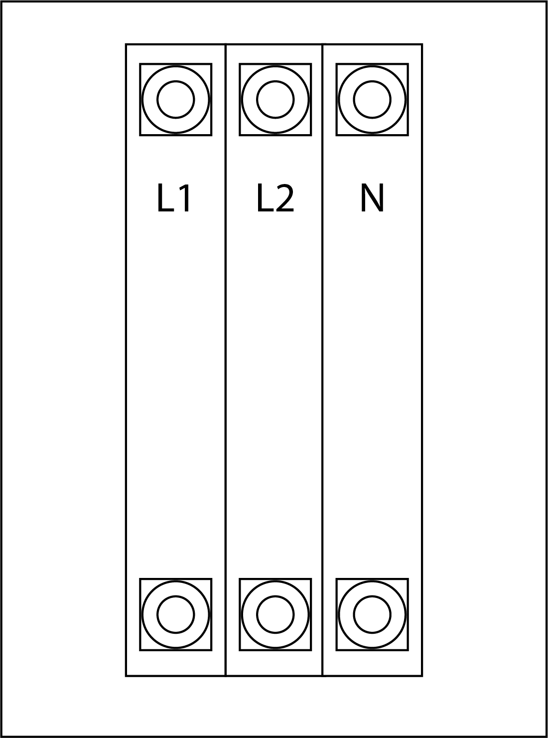
A 2-pole switch has two hot wires coming into it for 120/240 single phase. This also is a solid neutral design – the utility, generator and building neutral are permanently connected.
3-Pole
A 3-pole switch has three hot wires coming into it for 120/208, 120/240, 277/480, and 346/600 three phase. This is also has a solid neutral design – the utility, generator and building neutral are permanently connected.
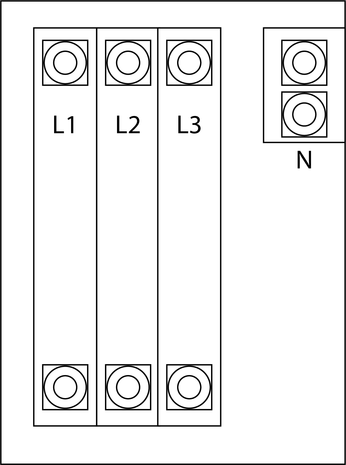
3-Pole Switched Neutral
A 3-pole switch has two hot wires coming into it for 120/240 single phase plus an additional pole for the neutral. A switched neutral will only allow the utility or the generator neutral to be connected to the building at a time.
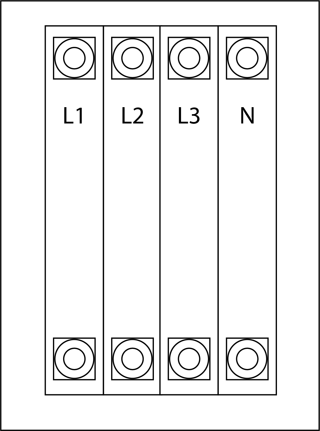
4-Pole Switched Neutral
A 4-pole switch has two hot wires coming into it for 120/208, 120/240, 277/480, and 347/600 three phase, plus an additional pole for the neutral. A switched neutral will only allow the utility or the generator neutral to be connected to the building at a time.
What are NFPA 70 700.3 (f) requirements?
The NFPA 70 700.3 (f) is a newer electric code specifically meant for a critical facility. These type of facilities already have an emergency generator in place. With the new code, these facilities now have to have a back-up power system in place for when their emergency generator is off-line. Simply put, you need a temporary back up generator for your permanent generator.
It is likely that you will be needing a portable/towable generator with a manual transfer switch. Your manual transfer switch will be installed after the automatic transfer switch and normally, there is a need for a docking station for the temporary generator.
For the visual learners:
For those who like the full technical definition:
2017 Code Language NFPA 70 700.3 (f)
Temporary Source of Power for Maintenance or Repair of the Alternate Source of Power. If the emergency system relies on a single alternate source of power, which will be disabled for maintenance or repair, the emergency system shall include permanent switching means to connect a portable or temporary alternate source of power, which shall be available for the duration of the maintenance or repair. The permanent switching means to connect a portable or temporary alternate source of power shall comply with the following:
- Connection to the portable or temporary alternate source of power shall not require modification of the permanent system wiring.
- Transfer of power between the normal power source and the emergency power source shall be in accordance with 700.12.
- The connection point for the portable or temporary alternate source shall be marked with the phase rotation and system bonding requirements.
- Mechanical or electrical interlocking shall prevent inadvertent interconnection of power sources.
- The switching means shall include a contact point that shall annunciate at a location remote from the generator or at another facility monitoring system to indicate that the permanent emergency source is disconnected from the emergency system.
It shall be permissible to utilize manual switching to switch from the permanent source of power to the portable or temporary alternate source of power and to utilize the switching means for connection of a load bank.
What should I do if my standby generator doesn’t crank or generator cranks and doesn’t run?
Step 1. Verify Generator Will Start and Run Manually
| ATS MODEL | COMMAND | PASS | FAIL |
| WINCO ASCO165 ASCO185 | Controller > manual mode > start command | Generator starts & runs: go to step 2 | Generator does start & run: repair symptom(s) |
Step 2. Put Generator In Auto Mode
| ATS MODEL | COMMAND | PASS | FAIL |
| WINCO ASCO165 ASCO185 | Generator in Auto Mode > Jump Auto Start contacts to start in Auto Mode | Generator starts & runs: Go to Step 3 | Generator does start & run: Repair symptom(s) |
Step 3. Give Start Command From Transfer Switch
| ATS MODEL | COMMAND | PASS | FAIL |
| WINCO | Flip toggle switch to start on the front pane | Generator starts & runs | Generator does not start & run: Troubleshoot the start switch continuity |
| ASCO165 | Press & hold the push to test button until the generator cranks & starts | Generator starts & runs | Generator does not start & run: Go to Step 4 |
| ASCO185 | Press & hold the transfer test button for at least 15 seconds | Generator starts & runs | Generator does not start & run: Go to Step 4 |
Step 4. Start Command At Transfer Switch Fails
| ATS MODEL | COMMAND | PASS | FAIL |
| WINCO | Manually bypass the switch start command & verify generator starts > Jump the Start Signal (#23) & Battery Negative (#1) terminals on the switch | Generator starts & runs: Go to Step 5 | Generator does not start & run: Troubleshoot generator start circuit. Problem is in wiring between ATS and generator start contacts |
| ASCO165 2-Wire Switch | Manually send the start signal to the generator > Apply jumper to generator. Hold jumper for at least 20 seconds. Closed on start Jump Terminal Block 7 terminals 4 and 5. Open on start (not used w/Winco products) Terminal Block 7 terminals 5 and | Generator starts and runs: Go to Step 5 | Generator does not start and run: Troubleshoot generator start circuit. Problem is in wiring between the ATS and generator start contacts |
| ASCO165 4-Wire Switch | Got to Step 5 | ||
| ASCO185 | Manually send start signal to generator > Apply jumper to generator. Hold jumper for at least 20 seconds. Closed on start Jump Terminal Block 7 terminals 4 and 5 | Generator starts and runs: Go to Step 5 | Generator does not start and run: Troubleshoot generator start circuit. Problem is in wiring between the ATS and generator start contacts |
Step 5. Simulate Power Failure
| ATS MODEL | COMMAND | PASS | FAIL |
| WINCO | Interrupt utility power to the transfer switch with the main switch in the Automatic position > ice cube relay should switch. You should open continuity between Start and Bat – terminals | Proper continuity between Start & Battery – terminals | Open continuity: Troubleshoot switch & relay wiring & function. Reset when finished |
| ASCO165 2-Wire Switch | Interrupt utility power to the transfer switch > start contact closed. Closed on Start = Continuity between terminal block 7 terminals 4 and 5 Open on start (not used w/Winco products) = No Continuity between Terminal Block 7 terminals 5 and 6 | Proper continuity, generator starts and runs: Go to Step 6 | Open continuity. If contact does not close when the utility available light goes out replace the ATS control board |
| ASCO165 4-Wire Switch | PART 1: Verify Voltages > Check voltage between Terminal Block 7 terminals 2(-) and terminals 3, 5 and 8 down. PART 2: Verify Crank and Run Signal > Interrupt utility/reset switch errors. Should have continuity between Terminal Block 7 terminals 7 and 8. Crank cycle is 10 seconds on/10 seconds off for three attempts. Should have continuity between Terminal Block 7 terminals 7 and 8. | Part 1: 12-15VDC: Continue to Part 2 PART 2: Generator starts and runs: Go to Step 6. | PART 1: Not VDC: Check generator battery, fuses and connections between switch and generator Part 2: No Run Signal and/or No Crank Signal: Replace ATS board. |
| ASCO185 | Interrupt utility power to the transfer switch > this should close start contact Closed on Start = Continuity between terminal block 7 terminals 4 and 5 Open on start (not used w/Winco products) = No Continuity between Terminal Block 7 terminals 5 and 6 | Proper continuity, generator starts and runs. Go to Step 6 | Open continuity. If contact does not close when the utility available light goes out replace the ATS control board |
Step 6. Reset System
| ATS MODEL | COMMAND |
| WINCO ASCO165 ASCO185 | Place transfer switch and generator in Auto Mode |
What if my standby generator doesn’t transfer and/or generator light doesn’t come on?
Step 1. Verify if Utility Available Light is On
| ATS MODEL | COMMAND | PASS | FAIL |
| WINCO | Not applicable: Go to Step 2 | ||
| ASCO165 ASCO185 | Start generator | Generator running, and generator available light is on: Go to Will Not Transfer troubleshooting steps Help Topic | Generator running, and the generator available light is off. Ensure plug is tight into the board: Go to Step 2 |
Step 2. Verify Generator Power At Switch
| ATS MODEL | COMMAND | PASS | FAIL |
| WINCO ASCO165 ASCO185 | Generator running > check L1-L2 voltage is 220-252 VAC on the alternate/generator source contactors of transfer switch | 220-252 VAC: Go to Step 3 | Not 220-252 VAC: Get generator power to the transfer switch. The breaker may be off or troubleshoot generator output voltage, wiring between generator and transfer switch |
Step 3. Verify Switch Harness
| ATS MODEL | COMMAND | PASS | FAIL |
| WINCO | Generator running and utility power off > check for voltage on Generator contact A1 and A2. | +/-120VAC. Replace generator contactor or coil | No Voltage. Trouble shoot harness/relay functions through the print. Once problem identified, restart test |
| ASCO165 | Turn off generator with switch in Preferred position. Check continuity from L2 to pin 1 and 7 on Plug 1. Check continuity from L6 to pin 6 and Pin 16 on Plug 1. Ensure plug is tight on board | Harness continuity: Replace board | Poor connection/continuity: Troubleshoot harness and repair |
| ASCO185 | Turn off generator with switch in Preferred position. Check continuity from L2 to pin 3 and 9 on Plug 1. Check continuity from L6 to pin 6 and Pin 10 on Plug 1. Ensure plug is tight on board | Harness continuity: Go to Step 4 | Poor connection/ continuity: Troubleshoot harness and repair |
Step 4. Verify Switch Settings
| ATS MODEL | COMMAND | PASS | FAIL |
| WINCO ASCO165 | Not applicable | ||
| ASCO185 | Turn off all power in the switch. Check the following settings: Switch 1 actuator 4 = Off (Down) 60 hz Switch 2 actuator 2 = On (Up) | Match. Replace board | No Match. Adjust switches and restart at first step |
What if my transfer switch won’t transfer to utility and/or the utility acceptable doesn’t come on?
Step 1. Verify if Utility Available Light is On
| ATS MODEL | COMMAND | PASS | FAIL |
| WINCO | Not applicable | ||
| ASCO165 ASCO185 | Make sure utility power breaker is open | Utility available light is on: Go to ‘Will Not Transfer’ help topic troubleshooting steps | Utility available light is off. Ensure plug is tight into the board: Go to Step 2 |
Step 2. Verify Utility Voltage at Switch
| ATS MODEL | COMMAND | PASS | FAIL |
| WINCO ASCO165 ASCO185 | With utility power available > check L1-L2 voltage is 220-252 VAC on the primary source contactors of the transfer switch | 220-252 VAC: Go to Step 3 | Not 220-252 VAC: Get utility power to the transfer switch. The breaker may be off or the power is still out, wiring between utility and transfer switch |
Step 3. Check Switch Harness
| ATS MODEL | COMMAND | PASS | FAIL |
| WINCO | With utility power on > check for voltage on Utility contact A1 and N. | +/-120VAC: Replace utility contactor or coil | No Voltage: Trouble shoot harness/relay functions through the print. Once problem identified, restart test |
| ASCO165 | Turn off generator with switch in Alternate position. Check continuity from L1 to pin 3 and 12 on Plug 1. Check continuity from L5 to pin 4 and Pin 15 on Plug 1. Ensure plug is tight on board | Harness continuity: Replace Board | Poor connection/continuity: Troubleshoot harness and repair |
| ASCO185 | Turn off generator with switch in Alternate position. Check continuity from L1 to pin 5 and 16 on Plug 1. Check continuity from L5 to pin 4 and Pin 8 on Plug 1. Ensure plug is tight on board | Harness continuity: Go to Step 4 | Poor connection/continuity: Troubleshoot harness and repair |
Step 4. Check Switch Settings
| ATS MODEL | COMMAND | PASS | FAIL |
| WINCO ASCO165 | Not Applicable | ||
| ASCO185 | Turn off all power in the switch. Check the following settings: Switch 1 actuator 4 = Off (Down) 60 hz Switch 2 actuator 2 = On (Up) | Match: Replace Board | No Match: Adjust switches and restart at first step |
What if my transfer switch won’t transfer?
Step 1. Check For Time Delays
| ATS MODEL | COMMAND | PASS | FAIL |
| WINCO | Not applicable: Go to Step 2. | ||
| ASCO165 ASCO185 | Press the Push to Test button to bypass the delays | Switch transfers to the next source. Note: ASCO switches will not transfer to a dead source | The switch does not transfer after time delays are bypassed |
Step 2. Does the Switch Work Manually
| ATS MODEL | COMMAND | PASS | FAIL |
| WINCO | Test with all power removed from the switch > manually press in the utility and generator contactor. Verify that both cannot be engaged together | Move Feely, contacts continuity when engaged: Go to Step 3 | Contacts don’t move freely, both contacts can engage together, no continuity when engaged: Replace contactor |
| ASCO165 ASCO185 | Test with all power removed from the switch > manually rotate handle on the left side of the contactor. | The switch transfers easily and smoothly. Go to Step 3 | Switch cannot transfer or is very difficult to transfer. Replace contactor assembly |
Step 3. Check Solenoid
| ATS MODEL | COMMAND | PASS | FAIL |
| WINCO | Not applicable: Go to step 4. | ||
| ASCO165 ASCO185 | Test with all power removed from switch > measure resistance of the solenoid | 35-70 Ohms: Go to Step 4 | Open/Out of pass range: Replace solenoid |
Step 4. Check Activation Signal
| ATS MODEL | COMMAND | PASS | FAIL |
| WINCO | Create a condition where the contactor should transfer. Monitor for AC voltage | 120 VAC. Replace contactor | No Voltage/Low Voltage. Replace switch, relay, auxiliary contact or harness |
| ASCO165 ASCO185 | Disconnect solenoid leads. Create condition where it should transfer and monitor for DC voltage | +/- 200VDC: Replace coil | No Voltage/Low Voltage: Replace Board |
What if my transfer switch goes back to utility, but my standby generator keeps running?
Step 1. Check for a start signal from the transfer switch
| ATS MODEL | COMMAND | PASS | FAIL |
| WINCO | Check continuity between Start and Bat – on switch | Continuity. The generator should be running | No continuity: Go to Step 2 |
| ASCO165 ASCO185 | Closed on Start = Continuity between terminal block 7 terminals 4 and 5 | Continuity: The generator should be running unless we are sure the time delays for cool down have expired. If the contact does not open after time delays replace transfer switch controller | No continuity: Go to Step 2. 185 Switches – check QV battery |
Step 2. Check if generator is in a cool down delay.
| ATS MODEL | COMMAND | PASS | FAIL |
| WINCO ASCO165 ASCO185 | Go to generator controller > Check to see if it is in a cool down delay. If so, wait for it to expire. Beware of stacked time delays | Generator in a time delay: Should be running. Go to Step 3 | Generator not in time delay but running: Troubleshoot generator or ATS board for improper shutdown |
Step 3. Adjust Time Delays to Prevent Nuisance Calls
| ATS MODEL | COMMAND |
| WINCO | Not applicable |
| ASCO165 | Fixed time delays. Can only adjust generator delays. Adjust the generator controller time delay to reduce stacked delays. Generator delay won’t start until transfer switch removes start signal |
| ASCO185 | Select the proper generator cool down and adjust Switch 1 Actuator 10 On (Up) 2 Minute Off (Down) 5 Minutes Adjust the generator controller time delay to reduce stacked delays. Generator delay won’t start until transfer switch removes start signal |
What should I do if my transfer switch exercise is not working?
Step 1. Verify Exerciser is Set
| ATS MODEL | COMMAND | PASS | FAIL |
| WINCO | Review programming | Set | Not Set: Set program |
| ASCO165 | Check exercise light to see if it is blinking for the approximate number of days until test | Light is blinking | Light is not blinking |
| ASCO185 | Check exercise light to see if it is on | Exercise light is on | Exercise light is off: Set exerciser |
Step 2. Verify Exerciser
| ATS MODEL | COMMAND | PASS | FAIL |
| WINCO | Set exerciser to set in near future. Verify 120V to the relay is present. Record hours or starts (if equipped) Return after test interval to verify | Generator running in test cycles | Generator has not tested |
| ASCO165 | This switch will automatically set it to exercise in 14 days. It is a long process. Record hours or starts (if equipped) Return after test interval to verify | Generator running in test cycles | Generator has not tested |
| ASCO185 | Set exerciser Record hours or starts (if equipped) Return after test interval to verify | When you start the exerciser, the generator automatically goes into test mode. | Generator has not tested |
Step 3. Exerciser doesn’t transfer load to generator
| ATS MODEL | COMMAND | PASS | FAIL |
| WINCO ASCO165 | Not applicable | ||
| ASCO185 | Verify board setting | Dip Switch S1 actuator 8 is in the up position. If load still does not transfer start Will not Transfer troubleshooting steps using the exercise under load circuit | Set dip switch and retest |
